ISTTOK Diagnostics
An overview of the main diagnostics existing in ISTTOK is given in this article. Most of them are available on the scientific literature so you can not expect a very deep insight on each one.
Índice
Magnetics
Electric probes
Spectroscopy
Interferometer
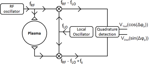
The ISTTOK interferometer is based on the heterodyne detection principle with quadrature detection for an absolute phase determination and has only one vertical line of sight that crosses the plasma in the radial center. The interferometer uses a central frequency of 100 GHz, crossing the plasma central cord. It can be used to measure densities up to 1.24 x 10^20 m-3. The signal from the RF oscillator and the same signal after crossing the plasma are then mixed with the local oscillator frequency (99.15GHz), resulting in an interference frequency of 850 MHz. Although more complex, this method with a intermediate frequency generation has the advantage of reducing the frequency to be acquired by the data acquisition system and improves the sensibility of the system. After the phase unwrapping one can retrieve the average plasma density across this cord.
Bolometry
Pyrometers
Heavy ion beam
The Heavy Ion Beam (HIB) is one of the most versatile plasma diagnostics allowing to measure plasma density, electron temperature, poloidal magnetic field and plasma potential profiles with high spatial resolutions. The temporal resolution of this diagnostic is also high enough to study fluctuations associated to the previously mentioned parameters. Unfortunately in large tokamak experiments the toroidal field is so strong that the required beam energy to travel along the plasma would be extremely high and for that reason these ion beams are limited to diagnose the plasma edge. Since ISTTOK vacuum vessel only has 0.20 m of diameter and relative low plasma density and toroidal field, it is possible to diagnose the plasma using this diagnostic since the ion beam is able to travel across the ISTTOK plasma, although it has some natural curvature mainly due to the toroidal field. The ISTTOK HIB (Figure 40) is able to operate either with caesium ions (Cs+) or with xenon ions (Xe+), but the ion beam current is higher in the case of Xe+ operation. In this mode of operation the HIB has the following characteristics: 22 keV of the energy, 15 μA of the intensity and 3 mm of the beam full width at half maximum (FWHM). After passing through the plasma, the ions that suffer additional ionizations (by electron collisions) are additionally deflected by the toroidal field since they have an additional positive charge (Xe2+). The detection system consists of two multi-cell detectors, one that collects secondary ions and the other that collects the primary ions that travel through the plasma without further ionisations and are only deflected by the magnetic field. The secondary detector consists in a column of 12 (6 × 12 mm2) flat copper cells separated by 0.3 mm for insulation. It is installed inside the tokamak vacuum vessel at the position calculated taking into account the primary Xe+ trajectory and the normal collisions pattern that produce the secondary Xe2+ ion trajectories in the ISTTOK magnetic field. The secondary ions enter the cells in the detector plane at about a 60◦ pitch angle. For the primary beam detection there is a matrix of 3x5 detectors to measure the beam deflection by the toroidal and poloidal fields inside the vacuum vessel.
Tomography cameras
Tomography is a very interesting technique by which a two-dimensional cross-section of a given three-dimensional sample can be viewed, just by taking measurements from the outside of the sample. This is particularly useful in Fusion because it allows the reconstruction of the plasma emissivity profile .
The tomography setup at ISTTOK is composed of 3 cameras: top, outer and bottom. Each one has a 22 element photodiode-array (PD-array), as shown in figure ???, but only the 16 central elements are used.
The photodiode-arrays and associated electronics are placed inside a brass cylinder which is covered on top with a copper-plated lid with a 0.8mm pinhole. This lid is shielded by ~3 mm thick piece of lead, to protect the device from the plasma and x-ray caused by runaway electrons. The inside of the cylinder and lid is coated with a layer of colloidal graphite to make it black and non-reflective. The three cameras are very similar in design and, consequently, have very similar signal gains, this isn't however enough to discard the need of a suitable calibration.
The devices are placed around the vessel as shown in figure Figure 2. The exact geometry of each one is explicit in table Table 1, where positions are measured from the center of the vessel. For the bottom camera, the flange is different and has a small 4,5mm spacer under the brass cylinder.
Note that: Port position + 2mm (O-Ring thickness) - Cylinder length - Lid thickness = Pinhole position
PD-array position = Pinhole position + Pinhole to PD-array distance
| (mm) | Port position | Cylinder Length | Lid thickness | Pinhole position | Pinhole to PD-array distance | PD-array postion | Cylinder diameter |
|---|---|---|---|---|---|---|---|
| Top | 138 | 41.6 | 1.55 | 97 | 9 | 106 | 37.8 |
| Outer | 148 | 39.8 | 1.10 | 109 | 9 | 118 | 37.8 |
| Bottom | 145 | 39.5 | 1.20 | 102 | 13 | 115 | 37.7 |

